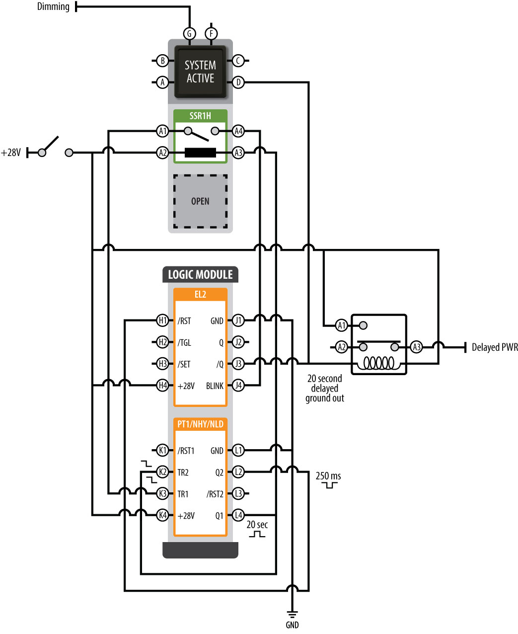
60 Best Of Time Delay Relay Wiring Diagram- A direct relay is used in the automotive industry to restrict and regulate the flow of electricity to various electrical parts inside the automobile. They allow a small circuit to govern a complex flow circuit using an electromagnet to direct the flow of electricity inside the circuit. They are usually labeled and identified upon the fuse bin panel. 


![WRG 2562] Time Delay Relay Wiring Diagram time delay relay wiring diagram new ponent time delay relay wiring diagram thermostat patent of time delay relay wiring diagram](https://lh3.googleusercontent.com/blogger_img_proxy/AEn0k_uht80iti7oOBsqOeg3s-fPBFMIVQhnwUMZTLlwwU8MMhUwTJuta-JsoyCwvQh1VdrbRfv-ef6Q_PTiHQGrSh-p7NJntiWZGeI_6e_o03RXHF47irb5Yci7tSOvaFJXipWp5-Pr8z2l-6iMu9lwC0K1i4JuLbvcSMuHyFW96bgZfTWHTmra-dQ-_wd7K3yO5Im43MCpcaRjIX4no5gx8fBbQDFx8aK1wrYV8NItGpit0RqkCm6SQOBbQLSMTSFIO0cyEoGsbKxnOrNsJ11gw2oIfbTwfrcshzvVurAjfqo5Hw=s0-d)

976 Electrical Symbols For Relays Wiring Diagrams

Contactor Wiring Diagram with Timer
A manage relay helps to prevent wires from overloading and overheating. Overheated wires can spark a fire. They reach not prevent volt spikes. If a relay switch stops working for some reason, it is practical to test it. This is totally applicable in automobiles, as one switch can control a large flow of electricity. As a result, if the switch shuts down, a fair share of the automobile will shut down.Many retailers will not accept returns on electronic parts. It is not too difficult to exam relays to ensure that they actually reach habit replacement before purchasing the part. The first share of identifying a bad relay is interim a visual inspection. A bad one will usually have burned contacts. Sometimes the friends can become in view of that corroded that they are green in color and do not permit any electricity to flow through them. topics time delay relay on delay timer time delay relays and solid state timers are used to provide the desired delay and timing functions though there are many types of timers and different functions they can perform they all e from two basic types which are on delay timer and off delay timer topics guard locking with time delay glt safety relay user manual the glt is a guard locking with time delay safety relay this safety relay is designed to use time delayed outputs for use in stop category 1 and to unlock a safety gate when the time expires it also provides a lock mand to lock a safety gate before the starting of the hazard topics the basics of time delay relays with an on delay timer timing begins when voltage is applied when the time has expired the contacts close — and remain closed until voltage is removed from the coil if voltage is removed before time out the time delay resets click here to see fig 1 f delay timers when using an off delay timer nothing happens when voltage is applied topics adjustable timer circuit diagram with relay output instead of 6v relay one can use 12v relay also but relay should be applied with 12v instead of 6v here the length of on time of the load is a multiple of 555 timer period output and number of outputs used in cd4017 suppose in this circuit 3 outputs of cd4017 are used so time of load is 3 times of t high and off time is 9 times of t high topics how to wire a relay the square relay pinout shows how the relay socket is configured for wiring this pinout image is only a 2 pole diagram for room on the page purposes but you can the picture here with this one since a 3 pole will just have 1 more set of contacts
√ 50 Best 12v Time Delay Relay Circuit Diagram
omron h3y 2 wiring diagram
In some cases, the cover is no question hard or impossible to remove. The part can be swapped later other partnered portion to see if the circuit is involved or not. If the swapped portion works, but the indigenous allocation does not, then a bad relay can be identified.The unaccompanied showing off to in fact test a relay to identify the extent of broken is in the manner of a meter. There are a few steps effective in examination this way. There are some general guidelines, and the first steps are usually the same.
Time Delay Wiring Diagram Wiring Diagrams All

240v Relay Wiring Dat Wiring Diagrams
WRG 2562] Time Delay Relay Wiring Diagram


