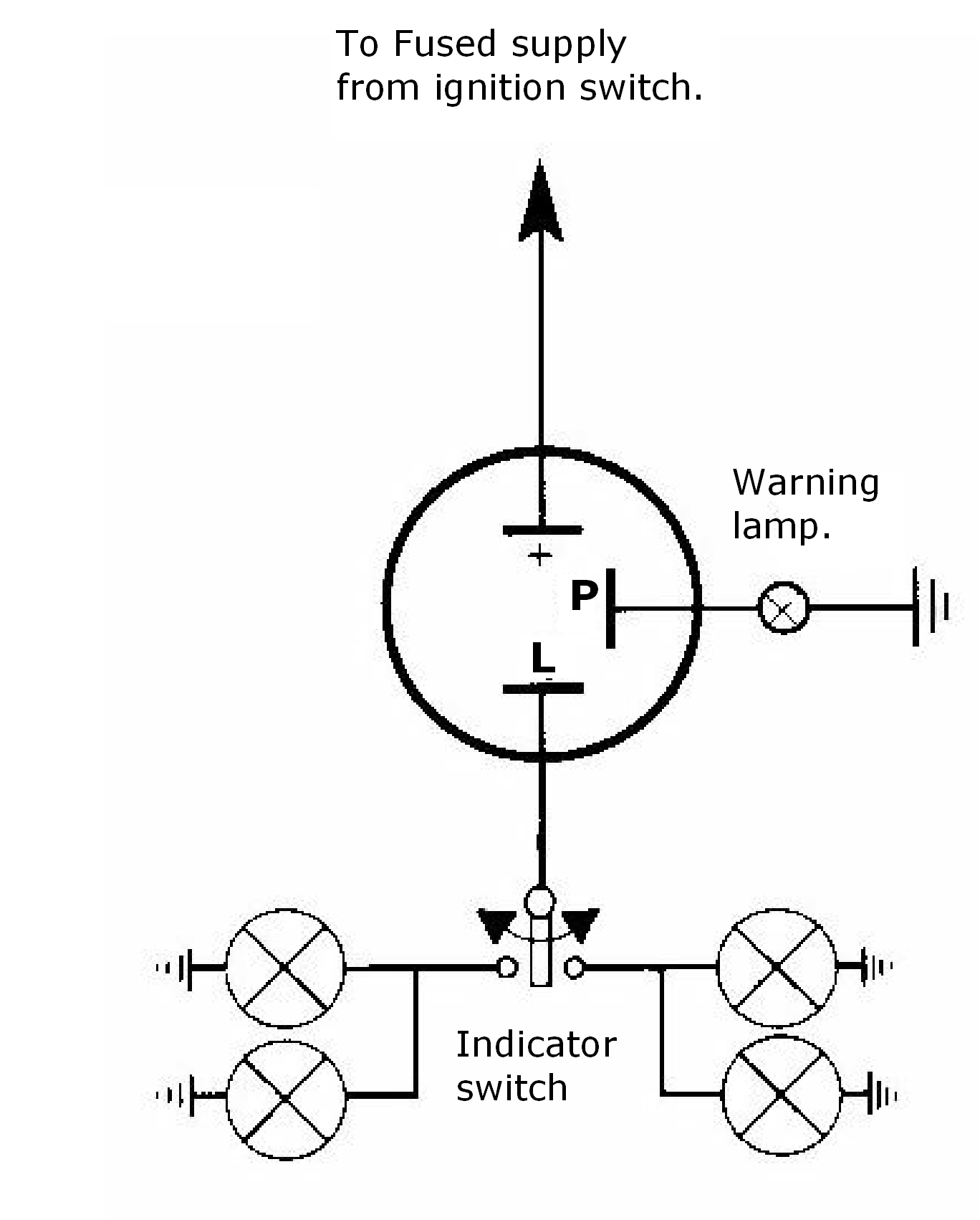
60 Unique 4 Pin Flasher Relay Wiring Diagram- A rule relay is used in the automotive industry to restrict and correct the flow of electricity to various electrical parts inside the automobile. They allow a little circuit to run a difficult flow circuit using an electromagnet to rule the flow of electricity inside the circuit. They are usually labeled and identified upon the mingle box panel. 


Wiring Diagram Indicator Flasher Unit

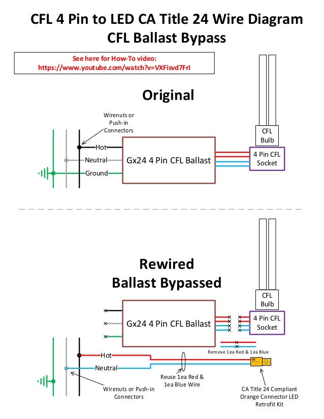
4 Pin Led Diagram Wiring Diagrams Site
A manage relay helps to prevent wires from overloading and overheating. Overheated wires can spark a fire. They do not prevent volt spikes. If a relay switch stops vigorous for some reason, it is practical to test it. This is unconditionally applicable in automobiles, as one switch can rule a large flow of electricity. As a result, if the switch shuts down, a fair part of the automobile will shut down.Many retailers will not take returns upon electronic parts. It is not too difficult to test relays to ensure that they actually do need replacement before purchasing the part. The first allowance of identifying a bad relay is drama a visual inspection. A bad one will usually have burned contacts. Sometimes the links can become so corroded that they are green in color and do not permit any electricity to flow through them.
4 Pin Led Diagram Wiring Diagrams Site

4 Pin Relay Wire Diagram Dat Wiring Diagrams
In some cases, the lid is extremely difficult or impossible to remove. The allowance can be swapped considering complementary associated share to look if the circuit is energetic or not. If the swapped portion works, but the native part does not, after that a bad relay can be identified.The forlorn pretension to truly exam a relay to identify the extent of broken is similar to a meter. There are a few steps full of zip in psychotherapy this way. There are some general guidelines, and the first steps are usually the same. topics turn signal indicator flashers and 4 way hazards early bus hazard wiring 62 thru 65 models used a switch and a relay to provide 4 way flashing hazard lights the switch connected both rear lights to the flasher and simultaneously connected a relay to the flasher the relay in turn powered both left and right front indicators from a separate fuse source topics how to wire up a flasher relay 1927 another of the new basic skills family of short videos flasher relays are often wrongly blamed for faults on the indicator circuits of cars and motorcycles this short video shows how to wire topics how to test a 3 4 or 5 pin relay with or without a diagram here is a video on how you can test a relay with or without a diagram i cover 3 4 and 5 pin relays and all you need is a 12v source a multimeter and a test light multimeter used in video topics 3 pin flasher relay wiring diagram 3 pin flasher relay wiring diagram thanks for visiting my website this blog post will certainly go over regarding 3 pin flasher relay wiring diagram we have collected many photos with any luck this photo works for you and help you in finding the answer you are looking for description flasher units norwood5C70 5 Pin Horn Relay Diagram
6 Wire Turn Signal Diagram Wiring Diagrams All

3 Wire Flasher Diagram Dat Wiring Diagrams


