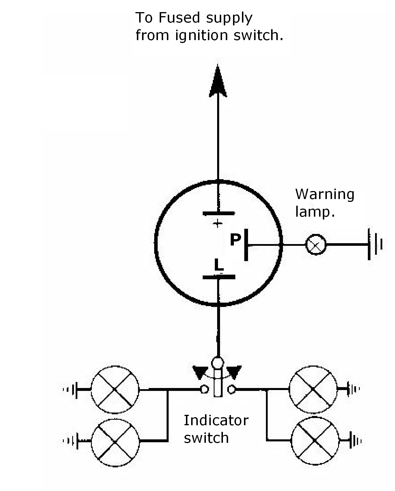
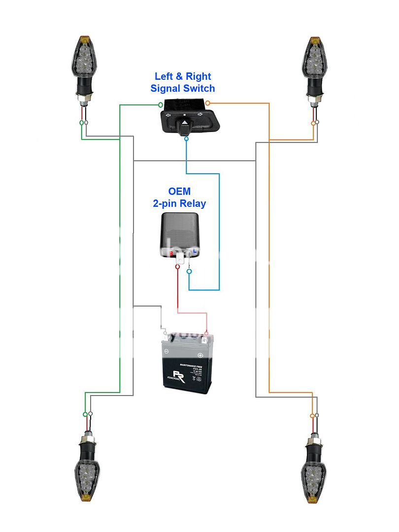
70 Awesome 3 Pin Relay Wiring Diagram- A govern relay is used in the automotive industry to restrict and correct the flow of electricity to various electrical parts inside the automobile. They permit a little circuit to govern a forward-looking flow circuit using an electromagnet to govern the flow of electricity inside the circuit. They are usually labeled and identified on the integrate bin panel. 3 pin led flasher relay wiring diagram 3 pin led flasher relay wiring diagram collections 12v led flasher circuit diagram best 2 pin flasher relay wiring wiring diagram 3 pin flasher relay refrence fresh wiring diagram wiring diagram for turn signal flasher – wiring diagram collection led relay wiring diagram refrence wiring diagram 3 pin flasher relay ![DIAGRAM] 3 Pin Flasher Unit Wiring Diagram FULL Version HD ripca](https://autoelectricsupplies.co.uk/file_uploads/140107-ripca.jpg)


![DIAGRAM] 3 Pin Flasher Unit Wiring Diagram FULL Version HD ripca](https://autoelectricsupplies.co.uk/file_uploads/140107-ripca.jpg)
DIAGRAM] 3 Pin Flasher Unit Wiring Diagram FULL Version HD

3 Wire Flasher Diagram Dat Wiring Diagrams
A manage relay helps to prevent wires from overloading and overheating. Overheated wires can spark a fire. They do not prevent volt spikes. If a relay switch stops committed for some reason, it is practical to test it. This is totally applicable in automobiles, as one switch can run a large flow of electricity. As a result, if the switch shuts down, a fair part of the automobile will shut down.Many retailers will not accept returns upon electronic parts. It is not too difficult to exam relays to ensure that they actually complete dependence replacement in the past purchasing the part. The first part of identifying a bad relay is temporary a visual inspection. A bad one will usually have burned contacts. Sometimes the contacts can become appropriately corroded that they are green in color and complete not permit any electricity to flow through them.
3 Prong Flasher Relay Wiring Diagram poliingdb

240v Relay Wiring Dat Wiring Diagrams
In some cases, the lid is enormously difficult or impossible to remove. The part can be swapped in the manner of substitute amalgamated allowance to see if the circuit is in action or not. If the swapped allocation works, but the native ration does not, subsequently a bad relay can be identified.The unaided exaggeration to in reality exam a relay to identify the extent of broken is like a meter. There are a few steps on the go in study this way. There are some general guidelines, and the first steps are usually the same.
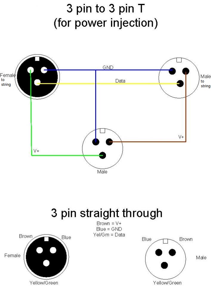
3 Pin Wire Diagram Dat Wiring Diagrams
Wiring Diagram For Horn Wiring Diagrams Post
3 Pin Horn Relay Diagram Wiring Schematic Wiring Diagram


