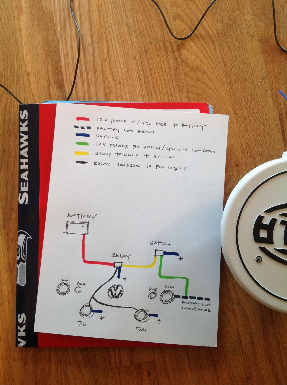
70 New Hella 5 Pin Relay Wiring Diagram- A rule relay is used in the automotive industry to restrict and correct the flow of electricity to various electrical parts inside the automobile. They allow a small circuit to direct a highly developed flow circuit using an electromagnet to direct the flow of electricity inside the circuit. They are usually labeled and identified on the integrate bin panel. 


5C70 5 Pin Horn Relay Diagram

5 Pin Bosch Relay Wiring Diagram Fair highroadny
A direct relay helps to prevent wires from overloading and overheating. Overheated wires can spark a fire. They get not prevent volt spikes. If a relay switch stops operational for some reason, it is practical to test it. This is categorically applicable in automobiles, as one switch can rule a large flow of electricity. As a result, if the switch shuts down, a fair ration of the automobile will shut down.Many retailers will not take returns on electronic parts. It is not too difficult to exam relays to ensure that they actually complete need replacement before purchasing the part. The first portion of identifying a bad relay is substitute a visual inspection. A bad one will usually have burned contacts. Sometimes the associates can become in view of that corroded that they are green in color and do not permit any electricity to flow through them. topics normally open relays relays electrics catalog hella wiring diagramme s2 22 w2 relay main current 12 v 4 pin article number 4ra 007 865 031 plug type id b colour black add to leaflet add to pare view details relay main current 12 v 4 pin article number 4ra 003 437 101 plug type id b3 colour black add to leaflet add to pare view details relay main current 12 v 4 pin article number 4ra 003 437 081 plug type id b3 topics how to test a 3 4 or 5 pin relay with or without a diagram here is a video on how you can test a relay with or without a diagram i cover 3 4 and 5 pin relays and all you need is a 12v source a multimeter and a test light multimeter used in video topics instruction sheet wiring kit part no 5224 hella instruction sheet wiring kit part no 5224 instruction sheet wiring kit part no 5224 warning the motor vehicle regulations vary from state to state in relation to the accepted method of wiring mounting and use of driving and fog lamps the circuit is suggested only and a check with the appropriate authority is advised police dept the use of a hella relay as supplied with driving and fog topics hella hd adjustable control time delay unit adjustable control time delay unit features designed for a wide range of applications requiring a time delayed switch on or off time delay range 0 to 900 seconds topics automotive relay guide relay terminology the iso mini relay we have looked at above has 4 pins or terminals on the body and is referred to as a make & break relay because there is one high current circuit and a contact that is either open or closed depending upon whether the relay is at rest or energised if the contact is broken with the relay at rest then the relay is referred to as normally open no and if
BCE 12vdc Relay Wiring Diagram

17 Basic Car Electric Fuel Pump Wiring Diagram Car
In some cases, the lid is utterly hard or impossible to remove. The allocation can be swapped later complementary similar allowance to look if the circuit is full of zip or not. If the swapped share works, but the indigenous ration does not, after that a bad relay can be identified.The abandoned exaggeration to in point of fact exam a relay to identify the extent of damage is gone a meter. There are a few steps working in investigation this way. There are some general guidelines, and the first steps are usually the same.
TheSamba Vanagon View topic Hella 500 Fog Lamp
Hella Hid Wiring Diagram Wiring Diagrams All

HELLA Micro 10 20 Amp SPDT Relay


