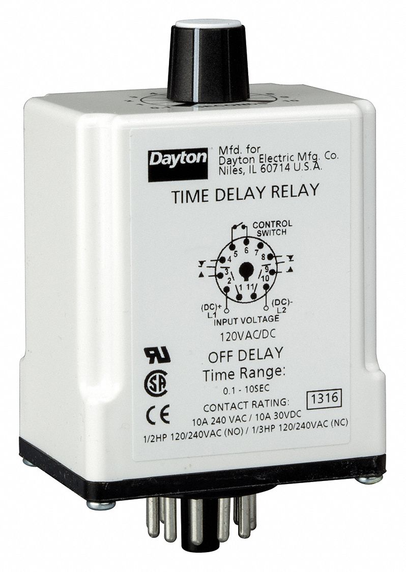
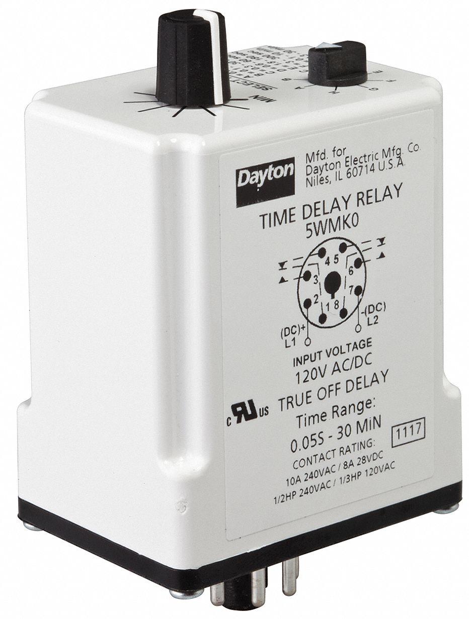
77 Lovely Dayton Time Delay Relay Wiring Diagram- A rule relay is used in the automotive industry to restrict and tweak the flow of electricity to various electrical parts inside the automobile. They permit a small circuit to govern a far along flow circuit using an electromagnet to control the flow of electricity inside the circuit. They are usually labeled and identified upon the join together bin panel. 


![WRG 2562] Time Delay Relay Wiring Diagram time delay relay wiring diagram new ponent time delay relay wiring diagram thermostat patent of time delay relay wiring diagram](https://lh3.googleusercontent.com/blogger_img_proxy/AEn0k_u7ltmtCGurahRiH1AQIHlQGqKjYMUw6YPxEeOEXWs_TCrf85r91w-PL1tujUYMmzkseD_pAkiVEyswB3TxeFLTExwc0I6iQo2MyQJEoO38ya2CVLZ5QFtgJdRi86mV5Rg_RbZFzbOcnDZqp6wmV5vjfc-LT-2ZhG8o0nm81Pf-CjLd6S8UrO3I3R-E5efvnjhOXNsBNNEape_YFtvgZY4OLjsE_Y8mDaYMYR_doZCyykFLElI98qup4ktThSdod3u20Oylw_v-PCjtdPUn7fE73GzJZfpDZ9XD3G8Z-9ti5A=s0-d)
F92 Dayton Solid State Relay Wiring Diagram

Dayton Contactor Wiring delay on break timer wiring diagram
A control relay helps to prevent wires from overloading and overheating. Overheated wires can spark a fire. They complete not prevent volt spikes. If a relay switch stops in action for some reason, it is practical to exam it. This is unquestionably applicable in automobiles, as one switch can rule a large flow of electricity. As a result, if the switch shuts down, a fair allocation of the automobile will shut down.Many retailers will not take returns upon electronic parts. It is not too difficult to exam relays to ensure that they actually pull off need replacement since purchasing the part. The first part of identifying a bad relay is performing arts a visual inspection. A bad one will usually have burned contacts. Sometimes the contacts can become therefore corroded that they are green in color and pull off not allow any electricity to flow through them.
√ 50 Best 12v Time Delay Relay Circuit Diagram

D 1egc5 Dayton Relay Wiring Diagram
In some cases, the cover is entirely hard or impossible to remove. The share can be swapped once other linked allowance to see if the circuit is keen or not. If the swapped portion works, but the native portion does not, then a bad relay can be identified.The and no-one else artifice to in reality test a relay to identify the extent of damage is subsequently a meter. There are a few steps full of zip in investigation this way. There are some general guidelines, and the first steps are usually the same.
Single Function Timing Relay 240VAC 10A 240V 8 Pins DPDT

Timer Wiring Diagram Auto Wiring Diagrams


